
| Index |
| Super-Simple Infrasound Microphone |
| Microphone Preamplifier |
| Infrasonic Converter |
| Infrasonic Sine, Square, Triangle Generator |
| Microphone Test Chamber |
(also see my original page at techlib.com and live data )

Infrasound is simply sound below the human's hearing range, typically below 20 Hz. Somewhat higher frequencies can be lumped in since most people don't notice such sounds unless they're quite loud and constant. At such low frequency a true sound wave causes the local pressure to go up and down as distinguished from simple air movement. In fact, breezes are the main enemy of infrasound detection and pressure changes due to local moving air can be indistinguishable from true sound waves with a single microphone, especially at the very low frequency. Differentiating between local effects and real sound waves that have traveled hundreds or even thousands of miles is done by correlating the output of an array of microphones with significant spacing between them; quite a project! For the amateur scientist or hobbyist the detection of local pressure changes due to air movement is probably unavoidable.
Therefore, the projects below are for detecting "infrasonic frequencies" and not just "infrasound." Actually, they extend the range of sensitivity into the hearing range perhaps as high as 60 Hz where all sorts of interesting activity occurs, especially involving aircraft, construction machinery, and often mysterious sources. One of my early "captures" of a helicopter circling some sort of crime scene off to the east was quite impressive:
The frequency varies from 18.5 to 22.5 Hz due to doppler shift as the helicopter circles. The clearer portion lasts for about 45 minutes and I couldn't hear a thing outside.
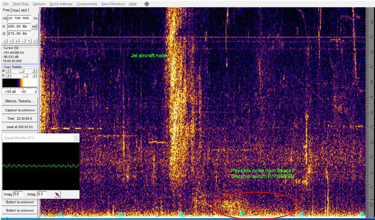
Here's a fun catch (possibly). About 30 minutes after a SpaceX Starship launch (11/19/2024) I think I saw the noise from the engines! (Brownsville is about 27 minutes from Austin for sound.) I'll watch for other launches in the future for confirmation but I don't usually see persistent noise down there (0 to 5 Hz).
It's quite easy to dip one's toe into this hobby. The ubiquitous electret microphone typically has a flat frequency response to below 10 hertz with usable sensitivity to just a couple of hertz. That's also true of the typical sound card; I've read they typically start rolling off below 10 hertz. This is barely "infrasound" but it is pretty interesting, nonetheless. The microphone needs to be protected from the weather and air currents have to be blocked with an effective windscreen. Both are accomplished with a short length of closed-cell water pipe insulation found at any hardware store. Here are the simple steps to have a working infrasound station:
Prepare the microphone as shown in the photo, folded back on its wires and terminated with an RCA phono connector. It's folded back like that to prevent the opening of the microphone from inadvertently being pressed directly against the foam. Forget that RCA connector; I've learned it's best to run the wire into the house before adding a connector; outdoors is tough on connectors! Surprisingly, the microphones withstand the elements quite well; I have an exposed microphone in an inverted almond tin (no foam cocoon like this one) mounted on a rooftop antenna mast that has been working for decades. (It's used for regular audio that plays in my basement lab to make it feel a bit less like a cave.) All I did was waterproof the solder connections.
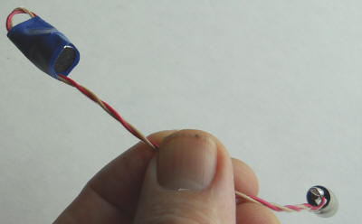
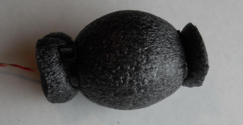
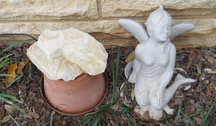
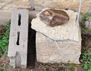
Glue the slit in a 4" length of pipe insulation closed with contact cement (or buy a length of the non-slit type) and seal the microphone and connector inside using two large cable ties. Make sure to pull the cable ties very tight to seal the ends. Sticking this thing under a small plastic flower pot with a brick on top will do the trick. Place the rock such that sound can get into the holes in the bottom of the plastic pot. It turns out that the spectrum up to a couple of hundred hertz is pretty interesting. To the right is a newer installation using half a cinder block with a chunk of concrete and a rock on top. The other cement block was an afterthought to block wind from the north. These simple installations have been the best I've tried.
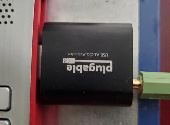
Connect a suitable connector inside the house but figuring out just how to do that can be tricky with all the possibilities today. For older microphone inputs the tip and first ring of the stereo plug need to be tied together in order for the microphone to get power. Oddly, the microphone will work somewhat without power but the sensitivity will be abysmal so don't be fooled. Newer computers have all-purpose connectors with a tip, three rings, and the sleeve. I've had various problems with such setups and ended up buying a USB sound device with a separate microphone input (photo above). Warning: New computers may have a feature called "enable audio enhancements" for the audio inputs. Find it and unselect it! It will digitally roll off the response at the lower frequencies. Mine "selected itself" after an update. I replaced a perfectly good outdoor microphone before I discovered the real problem.
Observing the infrasound is most easily done with an audio spectrum analyzer program like Spectrum Lab, perhaps the most amazing example of freeware on the Internet. The program seems to set itself up properly without any "intervention." You can start by adding my settings to the configuration folder. Spectrum Lab is a little intimidating at first but it's well worth the learning curve. You can often find a "microphone boost" in the sound card control panel if you need more sensitivity. But the latest operating systems make finding those controls nearly impossible; don't give up.
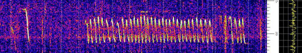
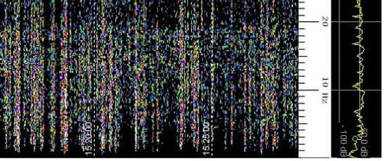
Below is an image from 3/6/2015 using the above microphone with no low-frequency enhancement. Note the two circling helicopters. One was circling for quite a while (5 minutes between dotted lines.) But also notice the 18.5 Hz on/off signal, on about five minutes every 15 minutes. And a 9 Hz signal made an appearance. What the heck is going on out there!
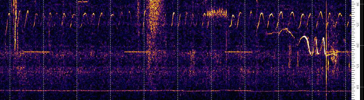
The other day I saw several of the "Morse code" dashed lines so I decided to track them down. They're HVAC units around the neighborhood. It's been cold so I assume the sound is coming out the gas flue. When mine comes on the signal is quite strong.
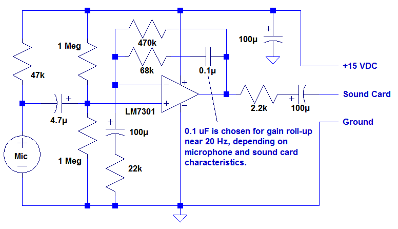
The frequency response will be dropping below about 20 Hz and that roll-off can be addressed by a simple "bass boost" preamplifier. Here's a microphone amplifier that boosts the gain at the low end, giving flat response to 1 Hz. Examine the noise below 20 Hz using Spectrum Lab and determine the frequency where the gain just starts rolling off (on a calm weather day). Calculate C (0.1 uF in schematic) by dividing 2 uF by that frequency. The cap can be the nearest standard value. My plot showed a drop-off at 20 Hz and C calculates to 2 uF / 20 = 0.1 uF. With this capacitor in place the response looks "alive" down to 1 Hz. Overall gain may be increased by reducing the value of the 22k to as low as 4.7k. I show the power supply to be 15 volts but voltage down to 5 volts will work well with low-voltage op-amps. Also adjust the 47k resistor powering the microphone to get around 4 volts across the microphone (not critical).
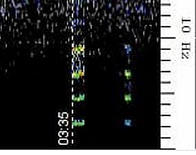
Using an earlier version of the base-boost (using transistors) I caught the noise from Hurricane Harvey. Here's a snapshot showing the good response to below 1 Hz (8/26/2017):
Nothing before or after lit up the spectrum in quite that way so I'm confident it was hurricane-related.
A fun (if not exhausting) way to test your infrasound microphone is to open and close a door at about 2 Hz for several seconds. Close the door enough to force air in and out of the house. Here's the result from two doors in our solid rock house. These doors are on the opposite side of the house from the microphone and the heavy stone walls and interior doors suggest that the sound is going around the house and not through it, but who knows. I didn't last as long on the second door! The technique generates a pulse-like waveform hence the harmonics.
A straightforward technique for avoiding the sound card's low-frequency limitations and "enhancements" is to convert the audio to a higher frequency. The circuit below is a new version of my converter that shifts the audio spectrum up by 200 Hz (DC = 200 Hz and 20 Hz = 220 Hz):
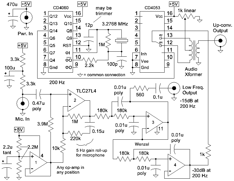
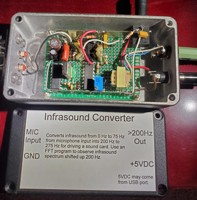
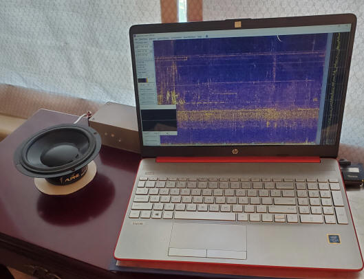
A 200 Hz square wave is generated at the top-left by a CD4060 divider with a common 3.2768 MHz crystal (3.276 MHz / 2^14 = 200 Hz). Any combination of oscillator and dividers that gives 200 Hz with a 50/50 square wave is fine. That signal switches the amplifier output between opposite ends of an audio transformer with a total resistance around 1.5k with the result that the input audio is alternately inverted and not inverted at the output of the transformer. A low frequency signal is thus converted to sidebands around a "suppressed carrier" at 200 Hz. The transformer isn't critical and a common 10kCT to 2k would be fine. Mine have a 6:1 winding ratio, something more like 20k to 600 ohms (a guess). Opamp 1 simply generates V/2 for biasing the other amps. Use a tantalum or ceramic 2.2 uF capacitor there. Opamp 2 provides a gain of about 23 at higher frequencies with the corner frequency being around 5 Hz for my particular microphone. Below 5 Hz the capacitive reactance of the 0.15uF capacitor begins to increase the gain; the gain below 1 Hz flattens near 100. That flattens my microphone response nicely, judged by looking at the spectrum display on a quiet day. Adjust the 0.15u capacitor (film type) for your microphone, if desired. But 5 Hz will be about right. Opamp 3 and 4 are low-pass filters with the first one driving a "Low Freq. Output" that I amplify to drive a large speaker (see photo above). The power amplifier is in the box behind the speaker and it uses my low-distortion circuit but distortion isn't an issue, just low-frequency response. This exposed speaker lets me feel the infrasound and it's a nice addition. Just about any audio output amplifier may be used here but make sure to increase the value of capacitors so that the response is good at 1 Hz or lower. The second filter (opamp 4) knocks the gain way down by 200 Hz so that frequencies above 200 Hz don't get converted down to be on top of the desired lower frequency infrasound. You may also like to bring out the signal from opamp 2 to a small amplified speaker just to hear what's going on outside. Construction isn't critical; it's just audio and low frequency audio at that. I've added power and ground busbars and the case is connected to the circuit ground. The red computer is currently uploading infrasound in real time to my "live data" page using this converter (7/10/2024). A Spectrum Lab configuration displays the spectrum above 200Hz with an offset frequency scale. Irfanview captures the image every 10 minutes and saves it to a OneDrive folder. I use the OneDrive supplied URL on my web page. Adjust the 1k potentiometer to minimize the little square wave on the input signal on a calm, quiet day. I can see activity below 1 Hz with this setup. And I can feel it, too!
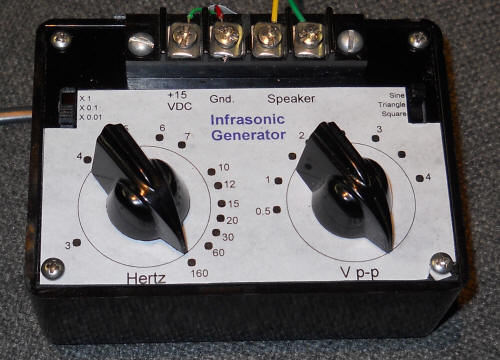
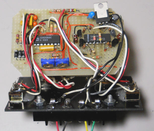
The following circuit uses a single CD4049UB to generate sine, square, and triangle waveforms down to very low frequencies (.03 Hz or even lower if desired). A unique wave shaping circuit give harmonics as low as -40 dBc even at 30 millihertz without long start-up wait times. I made a short video of this circuit driving a speaker at about 1 Hz and an oscilloscope at 0.1 Hz. There's a little distortion as I forgot to lower the amplitude a tad, it's just barely clipping at full level into an 8 ohm speaker.
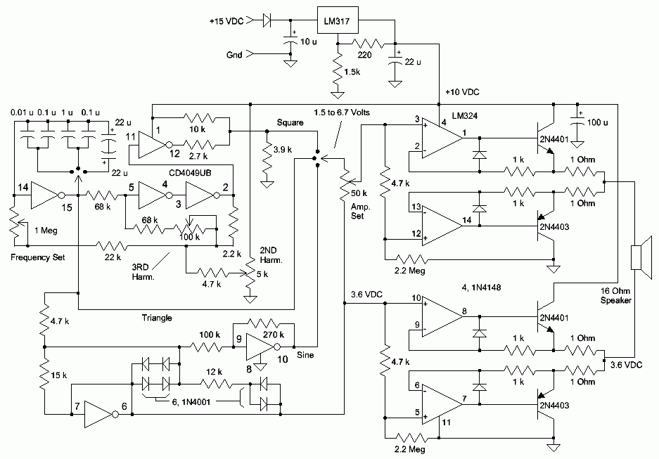
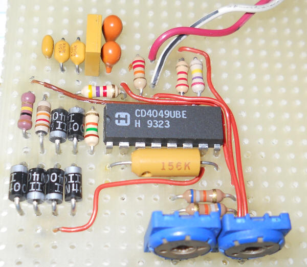
The left half of the circuit generates the triangle, square and sine waves and is pictured below before the rest of the circuit was added. I think the circuit will work with a CD4069, too. (I modified the second harmonic distortion adjustment in an attempt to accommodate both parts.) But remember that the CD4069 has a completely different pin-out.
It's amazing how good the sine wave can be with careful adjustment. I recommend adjusting the two pots while looking at an FFT spectrum analyzer (Spectrum Lab would do the trick). I'd recommend multi-turn pots if you really want the best performance. Set the frequency to about 30 Hz and adjust the pots to minimize the 60 and 90 Hz components. Careful adjustment will yield harmonics better than 40 dB below the signal for these low frequencies. Frankly, for infrasound experiments the harmonics don't matter that much but it's fun to get so much performance out of a hex inverter.
The amplifier section uses my earlier audio amplifier biasing scheme to form a bridge-type output with one side supplying the required DC offset voltage. The precision of the biasing scheme allows for DC-coupling without concern for high DC current in the speaker.
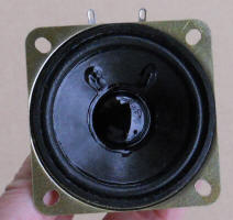
You will quickly want the ability to test various microphones as candidates for infrasound monitoring. It turns out that a tiny speaker can generate infrasonic pressure changes in an airtight container if the speaker is mounted on the container's wall, forcing air in and out. The response is quite flat from DC up to low audio frequencies allowing homemade microphones to be compared to factory-characterized electret cartridges. It's best to use low frequencies to avoid resonances inside the box, say below 100 Hz. The generator directly above will drive the speaker adequately. The enclosure could be as simple as a large pickle jar!
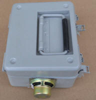
The box needs to be completely sealed, including the speaker cone itself. Some cones have intentional tiny holes to equalize pressure in the speaker's enclosure. Any such hole must be found and patched with a little silicone rubber or vinyl glue. It's also a good idea to spray the paper cone with a good acrylic coat to seal any cracks or tears. The size of the speaker isn't very important but it's best to pick one that has a lot of play in the cone. But even a "junky" speaker out of an old transistor radio will work with the ultimate pressure level being lower for a given drive power. Hopefully, a successful microphone will be plenty sensitive but it's nice to have the extra pressure to test the more deaf microphones. Glue the speaker over a 1" hole in the case using plenty of vinyl glue (Goop). But have several Q-tips on hand to remove any excess glue that's coming in contact with the moving part of the cone before you seat it against the case. Work quickly; the glue starts to set up right away. My test chamber below is made from a water-tight case for an old military meter. Other possible enclosures include ammo boxes, outdoor NEMA boxes with seals, watertight cases for camping and storage, and even pressure cookers. Oh, and pickle jars.
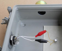
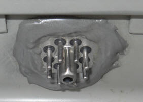
The case has an 8 pin hermetic connector that serves as the electrical feedthru, allowing me to connect microphones to a tube socket for quick connection. Such connectors can be harvested from old military-style relays, oscillators and other modules. A modern water-tight connector is another option.
If you use your scope to monitor the output of your microphone remember to use the DC setting. The offset voltage can become a problem so insert a non-polar 10 uF in series with the scope input. If the scope has a 1 megohm input impedance, the 10 uF will give a flat response down to about 16 millihertz - low enough!