

WWVB, JJY and MSF are time/frequency transmitters operating at 60kHz with their primary use having become the calibration of consumer clocks and watches. (Precision timing and frequency control tasks are now mostly accomplished using GPS.) Other frequencies used around the world include 25kHz 40kHz, 50kHz, 66.66kHz, 68.5kHz, 77.5kHz and higher. There is little chance that some of these services will be discontinued any time soon due to the rather large user base and suitability to micro-power reception. It turns out that the signals may be used for other experimental purposes such as solar flare detection during the daytime (read about SIDs or sudden ionospheric disturbance). And who knows what that strong but complex nighttime signal is hiding. It's also handy as a quick check of the accuracy of an oscillator in an instrument that can receive the frequency (selective level meters or even simple low-frequency SDRs).
| 60kHz Signal Generator |
| Inexpensive WWVB PCBs |
| Sudden Ionospheric Disturbance Monitoring |
| Oddball SID Detector |
|
The Deep End Over the top WWVB receiver |
| Live SIDs Data at techlib.com |
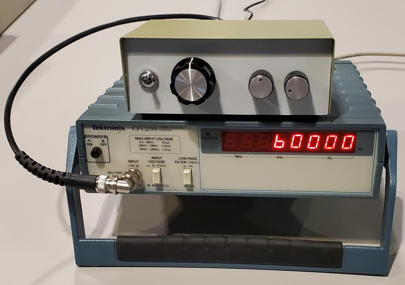
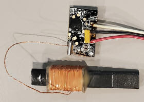
In order to play with WWVB and similar signals a couple instruments are recommended. An oscilloscope is a must and a signal generator with fine resolution is hard to beat. Consider all of your instruments as potential frequency sources; I was surprised to count seven suitable generators within sight at this moment! Instruments you might overlook include selective level meters like the HP3586 (lets me tune to 0.1 Hz!), the old Rockland/Wavetek 5100 synthesizer, "pulse" generators, "waveform synthesizers" and even bench audio oscillators - my antique Krohn -Hite 4300A is plenty stable for tuning antennas and filters. It's straightforward to use a frequency divider (perhaps a 74HC390) to divide down a high-frequency synthesizer. Divide down a 6MHz synthesizer with 100Hz resolution by a factor of 100 and you have 60kHz with 1Hz resolution. But it's also a simple proposition to build a custom oscillator for the job. Below is a generator that uses the inverters in a CD4069 as "pretty good" inverting op-amps and a "real" dual op-amp to boost and buffer the outputs.
The top three inverters form a sawtooth oscillator with the frequency set by the 1000pF capacitor, two potentiometers and associated resistors. The sawtooth is converted to a "squarish" waveform by the next inverter and the last two inverters are configured as band-pass filters right out of an op-amp cookbook. (Note the gates act like inverting op-amps (with somewhat low open-loop gain) with an internal positive input biased up to Vcc/2, saving two resistors.) The dual op-amp at the end should be pretty quick like the TL072 or many other "audio" types and the 82pF caps across the feedback resistor further reduce the harmonics. The output has a series 560 ohm resistor (near 600 ohms) for driving an audio attenuator for those times a very tiny signal is needed for directly connecting to a receiver. It's usually adequate to connect a clip-lead to the output, draping it across the antenna circuit to be tuned or to use a coil like the orange one below.
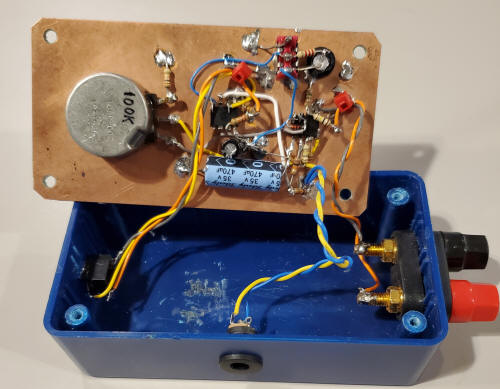
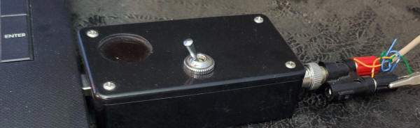
Note the unusual build below. The idea is to reuse the chassis by slipping out the breadboard and replacing it with a different circuit; many functions like this generator are only needed for a brief time. Just store the breadboards or protoboards in a box; they're inexpensive enough to treat like soldered PCBs.
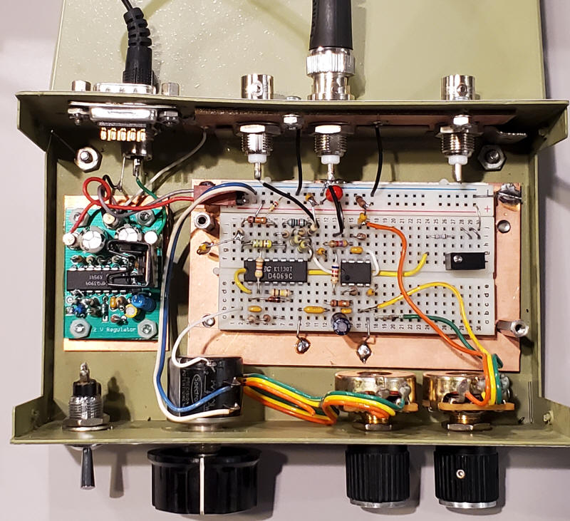
The breadboard or protoboard is mounted on a copper-clad ground plane board with several soldered ground connections (highly recommended). The ground plane and protoboard stay together and the assembly is held in place by the two long standoffs acting as easy-to-grab nuts (four didn't seem necessary but the bolts are there). Unplugging a few wires is all that's necessary to get the assembly out and this photo documents where to plug in the wires in the future if I want it back. (Truthfully, I have nice synthesizers so I'll probably just build another circuit in there as the need arises, still saving the labor that went into the case.) The regulator to the left stays with the chassis and that could be a simple three-terminal regulator or nothing if the external supply is regulated. The case is an old "A/B" network switch with extra hardware beyond what I used, including a 9-pin D-type connector, toggle switch, additional potentiometer and BNC. I covered the original holes with sheets of sticky-backed Lexan from old equipment labels (scrap from my company). When using a protoboard (PCB versions of the breadboard above) space the board up a bit to make room for solder and leads underneath and add a sheet of insulating material on top of the ground plane so that you can add parts from the top later without worrying about the leads hitting ground. Stop the insulation short along one long edge so that it's easy to add direct grounds to the ground strip on the board. Since it becomes a permanent assembly, there's nothing wrong with soldering one leg of a component to the edges of the ground plane, an example being the ground leg of an electrolytic capacitor for a high-current audio amplifier or voltage regulator.
When you decide to use this generator turn it on long before you need it in order to let the internal temperature stabilize. The frequency will drift fairly quickly for several minutes.
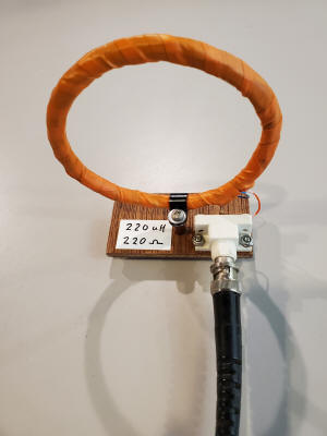
The coil below is a handy attachment for your signal generator. It consists of about 36 turns with a 3.75" diameter with a series 220 ohm resistor between the coil and BNC connector. None of these components are critical; I've used nothing more than a clip lead wrapped about three turns with a 50 ohm in series just to lighten the load on the generator. But this stand-alone induction coil is ready to use and with so many turns it will excite your loopstick antenna from a few feet away; just align the loopstick as though you were going to shoot it through the loop like an arrow. Don't place the loopstick too near the coil or some detuning will occur; perhaps 5 or 6 inches minimum.
Inexpensive receivers that include a tiny loopstick antenna, an AGC amplifier, crystal filter, and amplitude detector can readily receive the signals to provide the very slow digital time code. It's a fairly straightforward challenge to decode the data string even with a tiny PicAXE microprocessor (search picaxe.com to find an excellent example) but it's a dubious project since "atomic" clocks are readily available as inexpensive consumer products; I suspect most readers already have more than one! Below is a typical commercial board for receiving the time code. (I've added three wires and a tantalum capacitor across the power.) There are two power wires (red and black) and the time code output (white). It gives a good decode at night when the signal is strong. However, when I wrap a few turns of wire around the end of the rod and connect the ends to my rooftop active antenna (with a 68 ohm resistor in series) the circuit will occasionally give good decodes (for the whole minute) during the weakest signal part of the day. Quite an improvement! The coil above also works quite well as a "re-transmitter" of my active antenna's signal.
But, again, I'm not sure there's much point to making a clock! For a simpler approach to decoding and a display where you can watch the action as it happens consider building an extremely simple PicAXE decoder. You can make this work without even looking at the program if you don't care for such. You would need a PicAXE (08M2 in this case), the programming editor from picaxe.com and a programming cable from picaxe.com or a USB to RS232 converter (or even an older computer with RS232, usually a 9-pin D connector). Just connect the PicAXE to a serial port using the recommended interface (simple), paste the code into the free editor, use the editor to find the right com port (it will show you a list and then test your guess to see what type chip is connected), then click "program." That's really all it takes to have a programmed part. I put the recommended phono jack and two resistors right on the protoboard with the 08M2 PicAXE so I can reprogram easily. My PicAXE program simply sends the binary code to a LibreOffice (or other) spreadsheet by talking to an AutoHotKey script; the script "types" anything it receives, emulating a keyboard, to whatever program has the focus. It "navigates" around the spreadsheet, filling in the data; it's fun to watch. To get a sneak preview of the format just open the spreadsheet in LibreOffice. Here's a zipped folder with the necessary files. (Note on the AutoHotKey script for decoding the time code to a spreadsheet in the folder: I just tried it on a slower computer and discovered that it was not keeping up. I removed a delay I had put in the script to reduce the burden on the CPU and that fixed the problem. The CPU load sits at 25% (up from around 12%). That's high for what it's doing but it takes over the computer anyway since it is constantly typing. Remember you can pause the script by right-clicking on the green Icon to get full CPU power back and to pause the action.)
The PicAXE schematic is quite simple:
The WWVB receiver shares grounds and 5 VDC with the PicAXE. Choose an LED with a built-in flasher to remind you the PicAXE is active or it will start typing all over your work when you give a different program the focus; flip the pause switch before clicking away from the spreadsheet!
Serial In and Serial Out above may be connected to a PicAXE USB to serial adapter available from PicAXE.com and it's nice to have at least one of those, a known-good interface. Jump down to the paragraphs about programming the PicAXE and various Serial/USB options located below for a more detailed description of the issue.
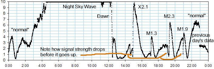
Sudden Ionospheric Disturbance detection relies upon the changing reflectivity of the lower ionosphere D region due to x-rays from a solar flare. WWVB operates at 60 kHz which is a bit high for SID detection except in lower latitudes. Depending on you latitude (southern being best) there is often a long stretch during the day when the signal gets quite weak. The lower D region becomes "foggy" to low-frequency signals when the sun rises and increases the ionization. Even though the signal could reflect off the higher E region, passing through the D region scatters the energy (not unlike fog or a cloud scattering sunlight). But when the extra x-rays from a solar flare reach the D region additional ionization occurs and that "fog" becomes more dense and starts to be reflective to LF signals. (The bottom of a "cloud" layer can become reflective, too, as I've witnessed!) The quality of the reflection is proportional to the intensity of the flare so simply plotting the signal strength can often give a nice plot of the flare's extra radiation. My location in Austin, Texas is pretty ideal in that the normal ionization is just high enough that the D region begins to become slightly reflective without a flare, especially in the summer months. As I explain, it's because we have this place called "West Texas" in between here and Boulder, Colorado, lots of intense sun! But in the winter months it doesn't work as well and the extra ionization from a flare might actually reduce the signal strength before increasing it. For those in higher latitudes it might be more effective to use a lower frequency signal, NAA in Maine being a popular one at 24 kHz. WWVB is hard to beat in that it's a constant signal with fixed power, bandwidth, modulation, etc. And they do their best to keep it on the air! Below is a capture of several flares during a fairly busy day in the late fall using the WWVB signal. One can see how some of the flares had to push the ionization level to the point of reflection by first pushing the level through the most opaque point; the signal drops before it goes up. The "normal" bumps (so labeled) occur because the "cloudiness" of the D region decreases to the point that reflections from higher layers starts to become "visible." Northern latitude hobbyists will be plagued by this for much of the year. The opposite is true south of the equator, of course. My plots here in Austin are best in the middle of summer.
See a "live" plot of the above at http://techlib.com/science/livedata.htm.
A simple receiver suitable for SID detection could be made from the loopstick and crystal of the previously mentioned commercial boards. One would resonate the loopstick, amplify the signal without AGC, use the crystal as a series filter, and finally amplify and detect the signal.
But there's a catch; those crystals are quite fragile with a maximum power dissipation of 1uW! It doesn't take much of a mistake to shatter one and a "proper" circuit that can't overdrive the crystal and provides some sort of AGC is best. But even then probing around with a scope probe or even a finger can zap the delicate crystal. A more robust but still relatively simple approach is seen in the Oddball SID Detector so named for the admittedly odd design approach. The amplified signal from a whip or loop antenna is mixed with a 60 kHz local oscillator intentionally tuned off frequency a tiny bit, just one or two hertz. The "beat note" is therefore targeted at 1.5 Hz. It's an "almost homodyne" receiver. I have various versions on techlib.com and a new straightforward version below; how you achieve the block diagram isn't critical:
It might look complicated but it's pretty simple, actually. The signal is converted down in one step to nearly DC so the receiver has twice the noise bandwidth of a more sophisticated superhet but the bandwidth is so low that it doesn't matter.
The tiny loopstick that comes with a commercial receiver will do the trick but it should be tuned after the amplifier is connected to compensate for the amp's capacitance. (Mine measures 1.9 mH.) Just lay a wire from your generator close to the loopstick but don't connect it.
Another approach is to buy a "pre-resonated" loopstick specifically designed for 60kHz. Search for 60kHz antenna and you will see an ad for the two I've tried from a Canadian firm. Just connect such an antenna to a low-capacitance op-amp amplifier with no tuning components as shown in the schematic below.
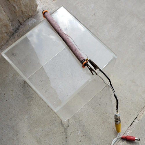
Alternately, wind your own loopstick and resonate it with a good capacitor. Ceramic types should be COG/NPO if possible but avoid "general purpose" dielectrics ( Z5U, Y5V). Other choices include polypropylene, polystyrene, glass (porcelain) mica or other high-Q (at 60 kHz) types. I would think that 1 mH would be enough inductance. Here are two I recently wound on fairly sizeable ferrite rods:
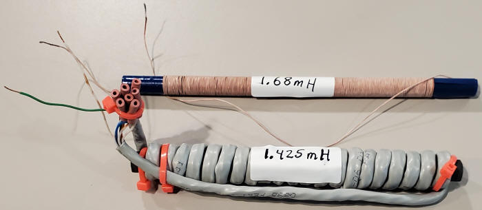
The first one is a traditional litz wound version and enamel wire would be fine, too. But the second one is a bit of a wacky idea. I wound it with Cat-5 cable (8-conductor) then, struggling to not make a mistake, I connected the ends of the windings to make a 22 x 8 = 176 turn winding. It works fine. On the other hand, it would have been just as fast to wind a single layer of enamel wire; the time savings didn't materialize! Plus it's a bit ugly to boot! The important point is that the coil isn't rocket science and most "worries" about such windings go away since we're receiving a single frequency; for example, extra capacitance due to the windings just changes the selected capacitors slightly. Size probably doesn't matter either since ordinary amplifiers can be so low in noise that the only consideration is whether the desired signal is competing with excessive local interference. Do heed that, however. Your project will work best if you place the antenna unit away from noisy appliances, the corner of an attic in the direction of the transmitter being near-ideal. My workbench is a terribly noisy place at LF! As an example, my "turned off" Siglent scope produces 60kHz interference.
I've chosen the commercial coil for this version of the Oddball SID Detector followed by a very simple amplifier because I want to lower the perceived difficulty; this is a pretty simple circuit!
Choose an op-amp with a GBW greater than 2.5 MHz (TL071, LF356, and many others). Watch that power supply voltage; many modern op-amps run only on lower voltage. (If you choose 5 volts for everything, switch to an 74HC4060 below.) I've built this active loopstick into a roomy plastic box and fastened the loopstick to the top, away from the small circuit board. When the case is upright the loopstick will be held away from the resting surface, helping to reduce detuning. Keep the receiver away from metal and point the loopstick at right-angles to the direction to the transmitter (Colorado, in the case of WWVB). Having the loopstick and first amplifier away from the rest of the circuit will reduce the possibility of feedback instability. Plus you can find an RF-quiet spot with a strong WWVB signal.
Note the standard 5.1mm x 2.1mm power socket to the left and female BNC to the right. Before you choose a "cheaper" alternative consider that 100' cables with BNC-terminated coax plus power are quite cheap thanks to security cameras (around $6 per cable). In the box of four 100' cables that I just bought were BNC bullets and BNC to RCA adapters, not to mention a large bag of cable anchors. Also, I did not capacitor-couple the output for one reasons: it's a quick health check to see the proper 6 volts (Vcc/2) on the cable since the loopstick is often in an attic, high shelf, etc. No cable termination resistor is needed at this low frequency (nearly audio) but do include the 100 ohm resistor at the op-amp. (If you prefer, drop that resistor to 75 ohms and lower the 10k at pin 1 of the CD4053 to 75 ohms also, giving better VSWR, even for higher frequency. You lose a little signal but your ham buddies will approve of the superior "match." )
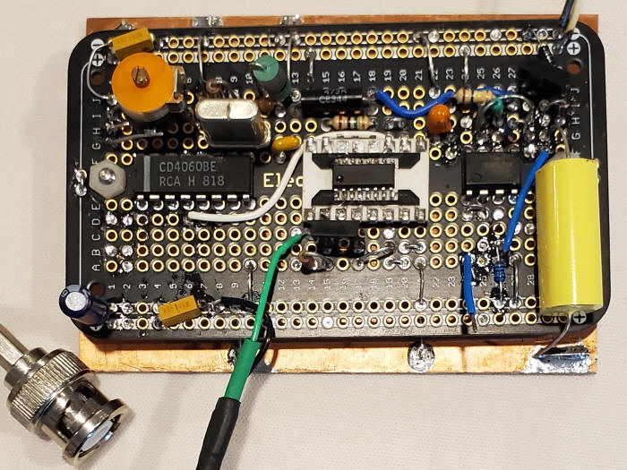
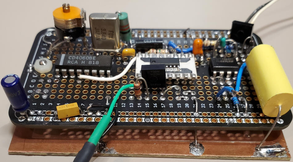
There are many ways to generate a 50/50 duty cycle crystal-controlled 60kHz square wave. Common crystal frequencies that are easily divided down include 6MHz (divide by 100), 4.8MHz (divide by 80) and 3.84MHz (divide by 64). You want the frequency to be near 1.5Hz off, either high or low. The first Oddball I built uses a selected 6MHz clock oscillator but I had a bunch to sort through. It's easier to build a crystal oscillator that can be tuned. To keep the parts count low I am selecting a 3.84MHz crystal and a CD4060 that provides both the oscillator and divider:
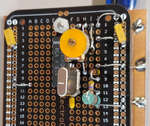
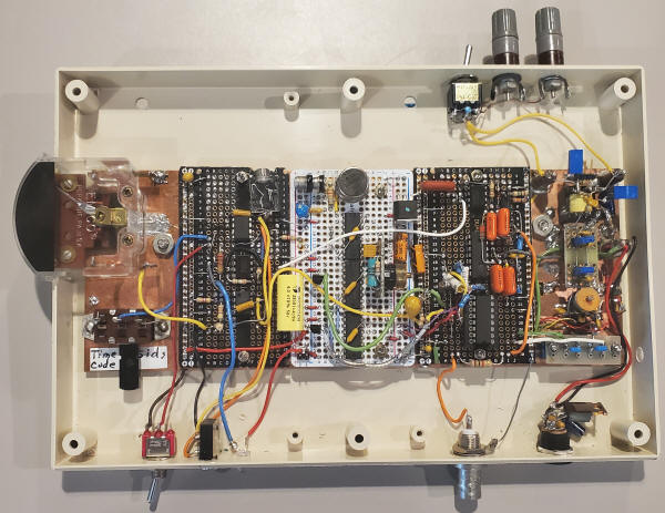
The complete receiver circuit is shown below. The oscillator is on the right side. (The 470 ohm may be reduced if the oscillator won't start.) Select either an inductor or capacitor to put the oscillator on the desired frequency (either 1.5Hz above or below 60kHz). It's a little easier to look at pin 7's 240kHz and adjust for a 6Hz offset but don't connect to the 3.84MHz since the probe might change the frequency a bit. Once the series component is installed, replace the 100pF capacitor with a 200pF trimmer to allow you to retune for the exact desired 1.5 Hz offset frequency when the project is complete. My selected component turned out to be a 22uH, the green vertical component at the bottom in the photo. Note the protoboard has a piece of copper-clad board below it for ground plane, always a good idea.
Note: after playing with the 60kHz crystals a bit I'd have to recommend a divided-down frequency reference like above; those 60kHz crystals are just too fragile for experimentation. The slightest overdrive and they shatter. They're rated for 1uW, max! Even if you have a perfect circuit, just probing around can up the drive level for the instant it takes to destroy the crystal. Same goes for using them as RF filters.
Parts Substitution Notes: The CD4060 needs 12 volts to oscillate at 3.84MHz; use a 74HC4060 for 5 VDC. The TLC27L7 should be a CMOS type that can operate on the chosen VCC and can sense input voltage near ground and swing near ground (pin 5 approaches zero volts with no signal). A "rail-to-rail" type will be fine but not reaching the top rail doesn't matter in this circuit. The CD4053 should work at 5 volts but I'd select a 74HC4053 for the lower VCC. The 4uF should be a polyester, polypropylene, or other low leakage type - not an aluminum electrolytic. The value isn't critical. The 1N5711 can be any number of Schottky small-signal diodes. Hobbyists in the USA can ask me for help obtaining parts.
The mixing is done by the CD4053 analog switch on the left of the schematic. The signal from the antenna drives pin 1 and a low-pass filter consisting of a 10k resistor and 1uF capacitor extracts the DC (near V/2 from the antenna circuit) for pin 2. Pin 1's signal will be oscillating around that DC value. Since the oscillator is 1.5 Hz off from exactly 60kHz, a 1.5Hz "beat note" will be present at pin 15. An RC filter removes the high frequency products and applies the nearly-DC signal to the positive input of the first op-amp.
(FYI, the CD4060 needs Vcc to be at least 9VDC to reliably start at 3.84 MHz. At 12VDC I had no trouble getting an 8MHz crystal to start. The 74HC4060 is much faster but can't handle 12 volts so choose ICs accordingly.)
The first amplifier (pins 1,2 and 3 in the schematic and 5,6 and 7 in the prototype) has a gain of 101 (set by 10meg and 100k). The 150pF reduces the gain at higher frequency. The output of the amplifier drives a traditional diode detector using two Schottky small-signal diodes and the resulting DC is buffered by the second op-amp. I like a film type capacitor for the 4uF but the value isn't critical; 3uF to 6uF should work well. 4, 1uF ceramics might be fine but electrolytics may be too leaky. The 10Meg and 4uF form a very slow low-pass filter; solar flares are slow and plenty of filtering will make the plots cleaner-looking.
The receiver circuit above fits on a small protoboard. I mount such boards above ground plane with numerous connections to circuit grounds. There's a sheet of fiberglass PCB material between the protoboard and the ground plane copper-clad board so that I can add components from the top without concern that the leads will hit ground. The blue wire sticking up from row 24 is the output DC signal that would be connected to a chart recorder, or more practically, to a data-taker sending values to a plotting program or spreadsheet.
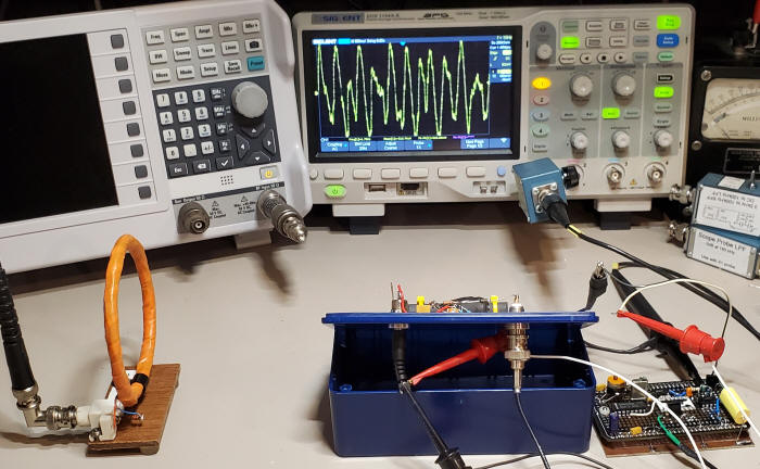
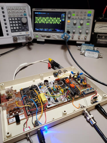
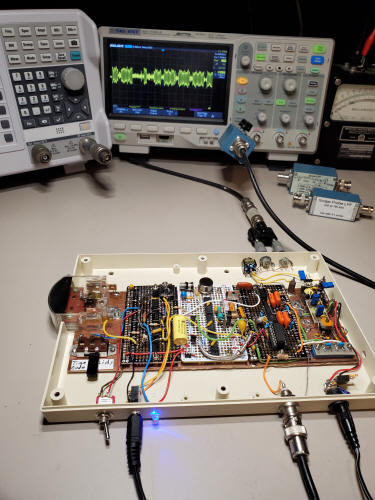
Here's all of it working. The orange coil is hooked to my rooftop active antenna (not needed for SIDs monitoring, just for this demo). The scope shows a jagged waveform that all but disappears if I disconnect the orange coil. This picture was taken in the morning when the signal is near its weakest point of the day but it's quite detectable (pretty large, actually) with the help from the external antenna. For solar flare detection, the loopstick is sufficiently sensitive when placed high and away from other electronics. The scope is connected to the first op-amp output, before the diode detector.
Note: the time code is now encoded on the signal's phase in addition to the amplitude so the scope won't show a nice, steady beat note but will show a chopped-up waveform as though you are rapidly pushing the invert/non-invert button on the scope. On my earlier SIDs receiver I have an analog meter connected to this voltage and it bounces around frantically. Fortunately, the diode detector doesn't care!
The final step is to measure the output of the last op-amp and somehow display the voltage vs time. In the old days I'd consider a Rustrak recorder but today a dedicated, obsolete laptop computer makes more sense. Below I present a PicAXE solution that costs just a few dollars, sufficiently inexpensive to make it a permanent part of the project. (I have a hard time dedicating a $200 USB data-taker to each project I build!) Don't worry; the PicAXE won't turn this into a "microprocessor" project instead of a SID project. They are super-easy to use and you can even avoid looking at the code if you like. The PicAXE will send data over a COM port to a PC AutoHotKey script that "types" the data into a spreadsheet (or any program that has the focus). I use Excel or LibreOffice because those two choices interpret a "ctrl :" as an instruction to insert the time of day into a cell. I've chosen to build the data-taker into its own box to avoid RF interference and to make it available for other uses. However, I've not given it many features since the big advantage of the inexpensive PicAXE is being able to dedicate it to a single purpose. I can reprogram it in seconds in the future if desired.
Parts Substitution Notes: The LM358 is a common op-amp and many substitutes are fine. The diode in the output helps the LM358 swing closer to ground but other op-amps can swing quite near ground, especially CMOS types. But make sure to select one that can handle 12 volts or connect pin 8 to the regulated 5 volts for the power (using a rail-to-rail op-amp and no diode in the output). The "flasher LED" contains circuitry that makes it flash; the PicAXE is not making it flash. The pot isn't a critical value; a 10k pot and 1k resistor would work as well.
Starting to the left, the 100k is to protect the LM358 from an inadvertent high voltage input and the 1meg pulls the input fairly low with no signal connected. The diode helps the LM358 reach zero volts out. The second op-amp provides a gain of 11 and the two 10k resistors on the output cut that in half; 1 volt on the input pin 5 will result in a 5 volt signal on the PicAXE pin 6. That resistor divider prevents the op-amp (running on 12V) from overdriving the PicAXE input (5V, max). Change the 10k from pin 7 of the op-amp to 12k if your op-amp is a rail-to-rail type; the LM358 only swings up to Vcc - 1.5 volts or about 10.5 volts with a 12 volt supply so equal-value resistors do the trick. Simply connect the second op-amp output directly to the PicAXE if the op-amp is running on 5VDC.
I cut a piece of copper-clad circuit board to serve as the lid, allowing me to build the circuit "dead bug" style right on it.
Turning the gain pot all the way down gives an input sensitivity of about 10 volts full-scale and all the way up gives full scale with 1 volt input. Absolute accuracy isn't required for SIDs, just adjust the pot for a good response to the large nighttime signal.
I recommend the flasher LED to remind you the circuit is sending data. Switch to pause when you want to take control of the computer. Otherwise it's like an annoying person sitting to your right randomly typing on the number keypad!
The "programmer" consists of two resistors and an RS232 serial port. I've shown the connections recommended by PicAXE.com and they have a nice USB to TTL serial adapter with a 1/4" stereo earphone plug wired like that shown. (The resistors allow the PicAXE to handle the higher voltages of a "real" RS232 port but TTL levels work, too.) I recommend a permanent stereo jack on every PicAXE project so it's a simple matter of plugging in the plug to reprogram or receive data from the PicAXE. You can make your own interface between an earphone plug and a 9-pin RS232 serial port by connecting the tip wire to pin 5 of the RS232 connector, the ring to pin 3, and the sleeve to pin 2. If your computer doesn't have a serial port you will want a serial-to-USB adapter but make sure to get one with a genuine Prolific or FTDI chip, remembering people lie on the Internet! The best bet is to get one from picaxe.com albeit a bit more expensive. Also read what picaxe.com has to say about such adapters.
Say you build the circuit above; now what? First, go to picaxe.com and download and install the free PicAXE editor. Second, figure out the RS232 solution discussed above for your particular situation. Third, plug in the connectors and run the editor program. On the left side you can "refresh" the COM ports and you should be able to recognize the correct one - mine says "COM12 ProlificUSB-to-Serial." Select it and then click "Check PICAXE type connected." If all is well it will confirm that your chip is properly connected and it an 08M2 type (and you remembered to turn on its power supply - gets me every time). Select 08M2 from the Simulation pull-down. Now copy my program, DatatakerforSIDs.bas and paste it into the program space to the right. Click on Home or PICAXE at the top and then the '"ABC check" to confirm the program is properly copied. Now click on "program" with the picture of the earphone plug and the program will download into the PicAXE. (Make sure you have the data-taker switch in the "pause" position with no flashing LED.) Close the editor program so that it "releases" the com port. Wait a few seconds and then run the AutoHotKey scrip on the computer and input the correct COM port (in my case I enter COM12). Now click on the cell in a blank spreadsheet and flip the switch to Run. Data should start to appear in the cells with the time of day followed by the voltage value. You may encounter problems along the way but probably not if you haven't make a wiring mistake; these things are really easy to use. There's a typical 24 hour plot spreadsheet in the zipped folder for this project. The zipped folder includes the PicAXE program, a 24 hour spreadsheet with graph for Libreoffice, and the AutoHotKey scripts, one is a ready-to-use .exe and the other is the AHK script that may be opened with AutoHotKey. (Download and install AutoHotKey to open the AHK script if you are concerned about running some .exe you found on the Internet!) Remember to close the script or editor when switching between programming and running; the computer can assign the com port to only one application at a time.
If you do have problems I highly recommend that you fight the battle until you win. Send me an email if you need assistance. The reason to not give up easily is that this is a really cheap way to get data directly into a spreadsheet or other document, cheap enough to embed the thing into the particular project. Take a look at other options and add up what it would cost to do the same job. I get numbers in the hundreds of dollars! And your plot won't look as good as one you make in Libreoffice. Also note that at no place above did I mention a programming language, compiler, etcetera! : )
Here are all the pieces less the power supply or two; it may be more convenient to run the data taker on its own supply since it might be some distance from the receiver. I am using a security camera cable that also has provisions for DC power.

My goal is to keep these projects simple but there's a slightly more complex option I really like. A dedicated RS232 to USB dongle is fine but it is also possible to connect the PicAXE to the computer using a "USB to TTL" adapter, basically the same device without the higher voltage RS232 circuitry. But you will want to use a software utility from the manufacturer to modify its firmware. This approach makes the project a simple, self-contained USB device. Make sure your selected USB to TTL device has a "genuine" FTDI chipset. The ones I like come in a plastic case:
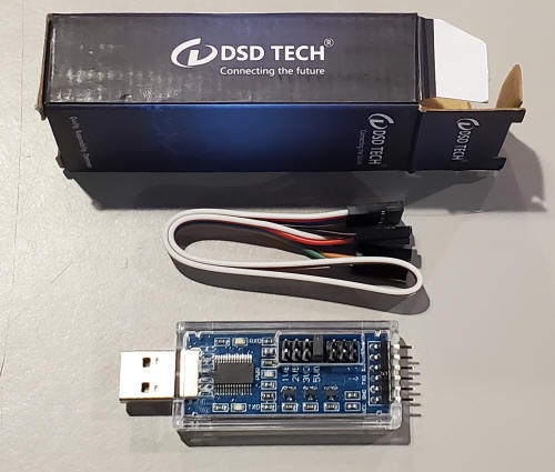
That's an FTDI chip next to the USB connector. Notice it has 28 pins; the less-desirable chips have fewer pins. There are cheaper versions than this brand that also have the genuine ICs, some as low as $4, including shipping, but getting burned by counterfeit parts isn't fun so take care. Avoid the ones with a "CH340" chip. I think the one above was under $15 with free delivery from that rather large retailer with the curiously fast delivery but the one below was two for eight dollars with free "Prime" shipping. But the unit below uses the Prolific chip so a couple inverters are needed. It's not uncommon for a project to have a couple unused inverters somewhere!
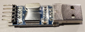
I usually use the FTDI chip because I found a utility on their website called FT_PROG that lets me invert the logic levels of the chip internally instead of adding inverter transistors or gates. (The original RS232 transceivers use simple inverting transistor circuits to handle the higher voltages, as high as +-15VDC and a minimum of +5 and a little more than -5, so logic devices like this chip typically generate "upside-down" signals by default to interface to those transistors.) Run FT_PROG, click on scan and parse (magnifying lens). You should see a chip type like FT232R. Click on the plus sign to the left of "Hardware Specific" and then click on the plus sign next to "Invert RS232 Signals." I change them all but I suppose TXD and RXD are adequate. Then select program devices, program. If you don't want to mess with that utility then a couple inverters will also work. I've used a mosfet transistor like the 2N7002 or BS170; just ground the source, connect the gate to the signal and connect the drain to plus through a 2.2k resistor. The drains have the inverted signal, one going in and one coming out. Or just use an inverter IC like the 74HC04.
These are cheap enough to build right into the project and you have a device that plugs directly into a USB socket without the need for a USB/RS232 converter. And there's 5 volts available, too. Here's an example of a simple device that currently plots my "live" SID detector output:
All that's in there is the DSD board above and the simple PicAXE circuit near the top of this page (below the commercial WWVB receiver board). I didn't even include the 22k and 10k resistors since the DSD board uses logic levels so it's just the PicAXE, pause switch circuit and a bypass cap. The input comes from an early version of the Oddball SID receiver with variable gain that amplifies the DC signal to 5 volts for driving the PicAXE directly so the dual op-amp with variable gain in this project above isn't needed. I cut a hole and added a red plastic window so I can see the flashing lights on the DSD board to tell it's "alive." I did remove their board from its plastic case so the USB connector would stick out of my case further. This has been plotting my live SID graph for years!
You may ask why I don't run everything on 5VDC and the answer is simply that many experimenters will have suitable parts on hand that require a higher power supply voltage. For 5 volt power, the antenna amplifier (LF356) could be replaced with a low-voltage op-amp but select one with a gain-bandwidth above 5 MHz. Change the CD4053 and CD4060 to 74HC4053 and 74HC4060. Replace the LM358 with a dual rail-to-rail op-amp, leave out the 1N4148 and connect pin 7 of that op-amp directly to pin 6 of the PicAXE, leaving out the resistor divider. And, of course, leave out the 5 volt regulator.
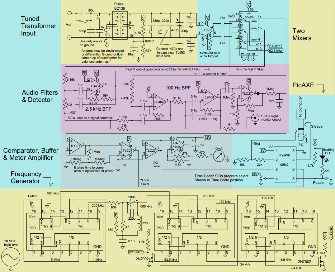
This "not-for-beginners" WWVB receiver features dual-conversion, an extremely flexible input circuit, active IF filters, and a PicAXE interface with two switch-selectable programs. The circuit got a little out of hand:
*An active antenna that drives a resistively terminated low-Z cable may be used
by opening the switch to add 100pF in series. Then retune.
**Logic level is suitable for decoding time code. DC level is a slowly changing
voltage suitable for SIDs plotting.
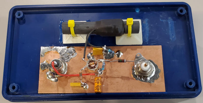
Starting at the top, the tuned transformer uses an older telecom transformer that may be resonated at 60kHz with good Q. (If you're in the USA, ask me about them. Remove "removethis" obviously.) The tuned transformer reduces the opposite sideband about 10dB but a typical tuned loopstick or other loop antenna will provide far more additional sideband rejection. The transformer's coupling is good enough to put the resonating capacitors on either winding; they simply add. Jumpers are used on many of the capacitors so that capacitance may be removed for resonating with un-terminated cable capacitance. Jumpers also allow for single-ended or differential connection. A 100pF capacitor may be switched in for driving the input with a low-Z terminated cable from an active antenna. Just dial out that extra 100pF with the trimmer cap and maybe the 220pF. As an example of how versatile this input can be, consider a very, very terrible antenna (first photo below), a tuned (tiny yellow cap by one of the clip leads) loopstick naively connected right across a 25' long security camera coaxial cable - what a terrible idea! The other end of the cable is attached to the input of the receiver with no proper termination resistor. But at 60kHz such a cable just looks like a pretty large capacitance, maybe 1,200pF (measure it to make tuning easier to figure). Simply remove the 1000pF and 220pF jumpers and tune the trimmer for maximum signal (best done with a signal generator). The signal is strong in the middle of the day with this loopstick at ground level on my back porch (see the scope in the middle picture below). The second scope picture to the right shows the input coming from a 50 ohm terminated cable driven by an active antenna (white body 50 ohm thru termination connected to a BNC to banana adapter). The 100pF is switched in and the signal is quite good; the 100pF prevents the 50 ohm termination from killing the Q of this input tank. I've gotten good results with a 3 meter wire thrown over a tree branch and fed into the lab using a similar coaxial cable with the wire antenna simply connected to the center conductor; a seemingly horrible antenna. Tune it up and there's a fine signal!
The transformer drives a differential amplifier, the TL592 (or LM733). My unit uses a 5k potentiometer for the TL592 gain resistor. The differential outputs of the TL592 are perfect for driving the CD4053 first mixer. The LO for the first mixer is at 62.5kHz, giving an IF frequency of 2.5kHz. The output of an active op-amp 2.5kHz filter drives the second mixer also driven by a 2.4kHz LO to produce a 100Hz IF frequency. A dual-section 100Hz filter follows and the output drives a precision rectifier (with gain) and a BNC output for observing the 100 Hz signal (scope pictures above). The rectified signal drives a self-adjusting comparator for observing the time code and the DC reference is buffered to drive a PicAXE analog input and amplified to drive a signal strength meter. The two LO signals are derived from a 10MHz clock oscillator that has provisions for fine-tuning. The one non-traditional section in the divider chain is the X3 multiplier that converts 200kHz to 600kHz since the 10MHz is "missing a three" for dividing down to 2.4 kHz. The two LO signals are amplified to 12 volts for the mixer using two 2N7002 transistors (or similar - a 2.2k base resistor would allow a bipolar NPN to do the same job). It's a bit over the top; here's what it looks like:
If you are in a particularly weak signal area you can add gain to the filters by lowering the series resistor at the input (say the 51.1k between the two 100Hz filters) and increasing the resistor to ground (actually 5 volts) to achieve the same parallel resistance (that would be the 1.33k at the bottom of the filter section). A 10k and a 1.5k would be pretty close and that would have a gain near 5 times higher. The switch on the PicAXE selects between the time decoder and a SIDs detector using the appropriate Libreoffice spreadsheet. Necessary files are in the zipped folder for these projects. I'm not sure what I'll do with this but building it was entertaining. I think I must like the smell of burning flux.