
Old telephones that plugged into a wall socket have all but disappeared. Quite a few are in closets and junk boxes, however. Here are a few fun ideas for these relics.
Caution: The circuit generates a high voltage that can shock.
The Phone Ringer circuit will work with any ordinary phone including older mechanical bell ringer types. The circuit rings the phone in a completely realistic manner until someone answers. When the receiver is lifted the user hears the audio of your choice. It might be another telephone, a tape recording, a favorite talk radio show, a fake busy-signal, a scanner tuned to weather or police, cues for the actor who forgot his next line, or whatever audio source strikes your fancy. DC current is passed through the phone to activate the phone’s electronics. This circuit is a slight improvement over my original version so that it can work with "modern" phones (circa 1980) that require more voltage across them to run internal electronics.
Do not connect this circuit or the phones used with this circuit to an actual
phone line, assuming you still have one. The phone cable will have red and green
wires which are simply connected to the points indicated by the schematic as "to
telephone." Polarity should not matter.
The circuitry is simple and not particularly critical. The first two inverters
form a slow pulse generator which controls the ringing rate. Change the 0.22 uf
capacitor to change the ringing rate and change the 22 Meg. resistor in series
with the diode to change the length of the ring. The second two inverters
generate the 20 Hz ringing signal. This frequency can be changed by changing the
.033uf capacitor. Mechanical bell ringers have a resonant clapper and should be
driven with a frequency near 20 Hz but a slight variation may give a better
ring. The last two inverters buffer the ringing signal and drive the two output
transistors. Practically any transistors can be used for the output including
2N4401 and 2N4403 but power transistors in a TO-220 package might be more
desirable if a lot of ringing is anticipated. I like the TIP32 and TIP31 for
those spots. The transistors should be capable of handling several hundred
milliamperes. Any low-leakage signal diodes will work for the 1N4148s.
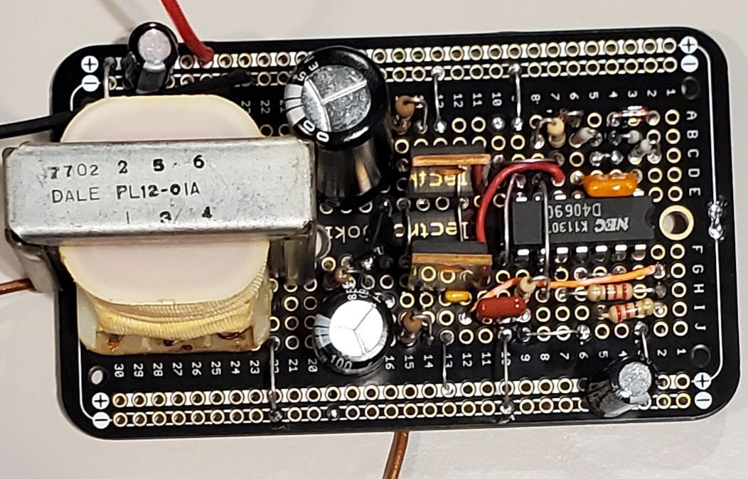
The power transformer must handle 20 Hz with at least some efficiency so it is
best to use larger units. Molded transformers will work fine but of course they
cannot be DC types which have built-in rectifiers. Choose a transformer with a
low voltage winding rated for an output voltage well below the DC power supply
used. The circuit as shown runs on 12 volts with a 9 volt transformer. A 6 volt
filament transformer powered by the circuit as shown will give a quite strong
ring. Reduce the 10 ohm emitter resistors to 4.7 ohms to get more ring power if
power transistors are used . (Don't leave them out entirely since they help
prevent high frequency oscillations.) I've had good luck with fairly small
transformers weighing just a little over 3 ounces (two different brands). My
prototype doesn't include the audio source input and the 470 ohm and capacitor
simply connect to ground.